


System Architecture
1 System Architecture
1.1 Overall Architecture
The RFID asset management system utilizes a centralized network-based interactive management approach. Data from computer room modules at each location is controlled and managed by a central host. In addition to aggregating RFID-collected data, the monitoring host also centrally manages user, permission, node, computer room, and device information, and sets unified alarm policies.
Data transmission between monitoring nodes utilizes an IP-based solution.
Computer rooms and warehouses are monitored on a unified business platform, achieving seamless online and offline integration.
The system consists of RFID asset monitoring units, computers, servers, RFID middleware (data collection server), and system software. The following diagram shows the overall system architecture:
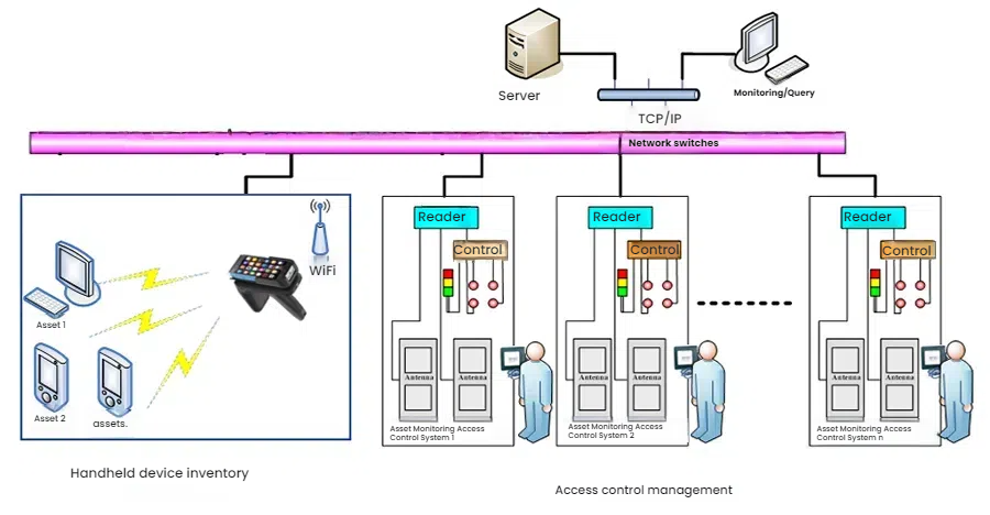
1.1.1 Handheld Inventory Management
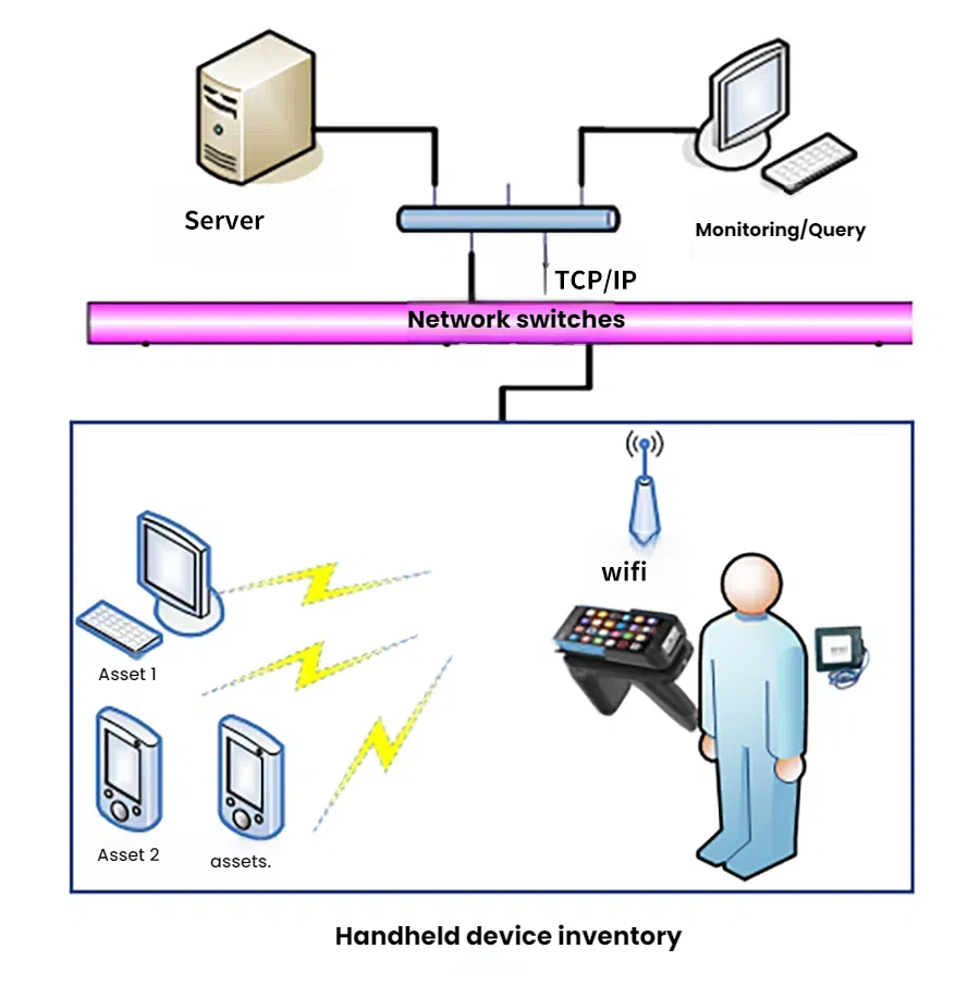
This ultra-long-range RFID reader/writer is based on the Impinj R2000 reader/writer chip and supports BLE 4.0 data communication. It features low power consumption, multiple data interfaces, and a simple human-machine interface, making it suitable for fixed asset inventory. If there are discrepancies in the information, management personnel can use the handheld reader to conduct on-site verification and modify the system or on-site information to complete the asset inventory.
1.1.2 Access Control and In/Out Management
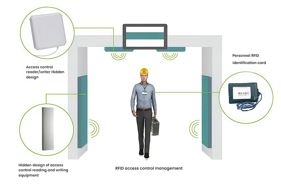
This fixed, custom RFID access control system is based on the Impinj R2000 reader/writer chip and is a UHF RFID reader/writer developed specifically for warehousing and asset management. Designed and constructed to meet customer needs, it automatically identifies and counts all incoming and outgoing materials, assets, and other commodities, collecting basic data. It features high sensitivity, strong interference resistance, stable performance, aesthetic appeal, and excellent concealment. When assets enter and exit the warehouse, the RFID access control system simultaneously identifies the asset's RFID tag information and the RFID tag information of the person entering and exiting the warehouse. Based on the system's administrative permissions, it verifies the identity of the recipient. If there is a discrepancy or if the recipient's information is not detected, the system will automatically trigger an alarm.
3D detection, no false alarms or missed alarms
Flow counting function
Acoustic and visual alarm function
Sensor activation function
Built-in imported reader for high stability
1.2 RFID System Components
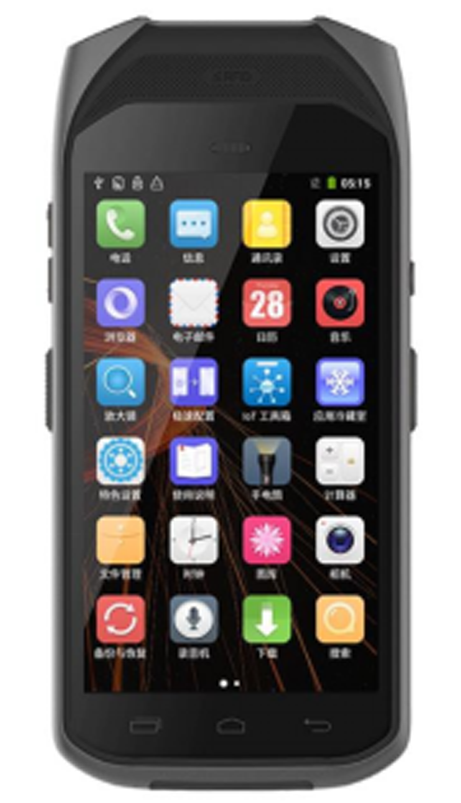
1.2.1 RFID Handheld Device
This handheld reader/writer, with a built-in antenna, is used for asset inspection and inventory. It quickly reads electronic tags on devices and transmits the read tag information to the backend server via the built-in GPRS wireless communication module for processing (or stores the read data and then copies it to the backend server).
1.2.2 RFID Electronic Tags
Fixed assets come in a wide variety of types and sizes, primarily categorized into a few types. Metal interference has long been a challenge in the application of RFID technology. To address these challenges and ensure ease of attachment to assets of varying sizes, we offer specialized labels and hangtags suitable for assets of varying sizes. The tags' built-in antennas are specially designed and packaged to provide excellent resistance to metal interference.
1.2.3 RFID Fixed Access Control Reader
This RFID access control channel is an ultra-high frequency (UHF) RFID channel specifically developed for warehousing and asset management. It automatically identifies and counts all incoming and outgoing materials, assets, and other goods, automatically collecting basic data. It features high sensitivity, strong interference resistance, stable performance, and is easy to install, debug, and maintain. When assets enter and exit the warehouse, the RFID access control system simultaneously identifies both the asset's RFID tag information and the RFID tag information of the person entering and exiting the warehouse. Based on system management permissions, it verifies the identity of the recipient. If a discrepancy occurs or if the recipient's information is not detected, the system will automatically generate an alarm.
Customized installation and construction can also be performed based on customer-specific on-site design.
1.2.4 RFID Card Issuer
Data is written to electronic tags based on customer needs and stored in the backend, primarily implementing tag information conversion.
2 RFID Asset Management System
The asset management system primarily includes software that implements system functions, including daily asset management, monthly asset reporting, comprehensive asset query, asset inventory, and asset system maintenance.
2.1 System Functions
2.1.1 Daily Asset Management
This primarily involves daily tasks such as adding fixed assets, warehousing, issuing fixed assets, transferring fixed assets, modifying fixed assets, deleting fixed assets, and calculating depreciation and residual value rates.
2.1.2 Asset Inbound Management
The process of registering, inspecting, receiving, and warehousing assets after they arrive, and generating corresponding vouchers. Inbound operations include purchase, transfer, lease, repair, return, surplus, and other inbound management. Inbound assets are managed based on the asset's code, name, specifications/model, and quantity.
2.1.3 Asset Outbound Management
The asset management department manages asset outbound transactions based on the asset's code, name, specifications/model, and quantity, as documented in the asset outbound voucher issued by the receiving department or the business voucher for accounting adjustments.
2.1.4 Asset Depreciation
This includes accruing monthly depreciation for fixed assets and printing monthly depreciation reports.
2.1.5 Fixed Asset Monthly Report
Query monthly (annual) statistical reports, monthly reports on added fixed assets, monthly reports on reduced fixed assets, and monthly (annual) reports on fixed asset depreciation based on company, department, and timeframe, and print functionality is available.
2.1.6 Comprehensive Fixed Asset Query
Query the status of individual or batches of fixed assets. Query criteria include asset card, custody status, active asset information, departmental asset statistics, retired assets, transferred assets, historical assets, name and specifications, start and end dates, company or department.
2.1.7 Inventory Function
Compare RFID handheld data with the database and process any normal or abnormal data to determine the actual status of fixed assets. Generate detailed inventory surplus and shortage reports, and inventory summary tables by company or department.
2.1.8 System Maintenance Function
System administrators can add, modify, and delete assets in the asset classification code table, exit method code table, purchase method code table, storage location code table, department code table, custodian table, and unit name table.
Operators are allowed to modify their own passwords.
System administrators can freely set the operational permissions for each subordinate operator.
2.1.9 Security Management Function
Various security management measures are provided.
Password Management Function: Maintain accounts and passwords.
Permission Control Function: Users are divided into different levels to determine their system access permissions, and different operations are determined based on different permissions.
2.2 System Process
Asset management includes operations such as asset addition, transfer, idleness, retirement, repair, and inventory. It encompasses the entire process of equipment from factory delivery, commissioning, to retirement. Equipment is factory-installed with an electronic tag, which contains asset information. Each time an asset management operation is performed, the reader reads the asset's electronic tag and sends the information to the server for processing, enabling asset tracking and management.
2.2.1 Adding Assets
Enter the relevant information for the device to be managed in the card issuance process and save the record to the database. The electronic tag containing the asset information is attached (or hung) to the asset according to regulations. This process involves three main steps:
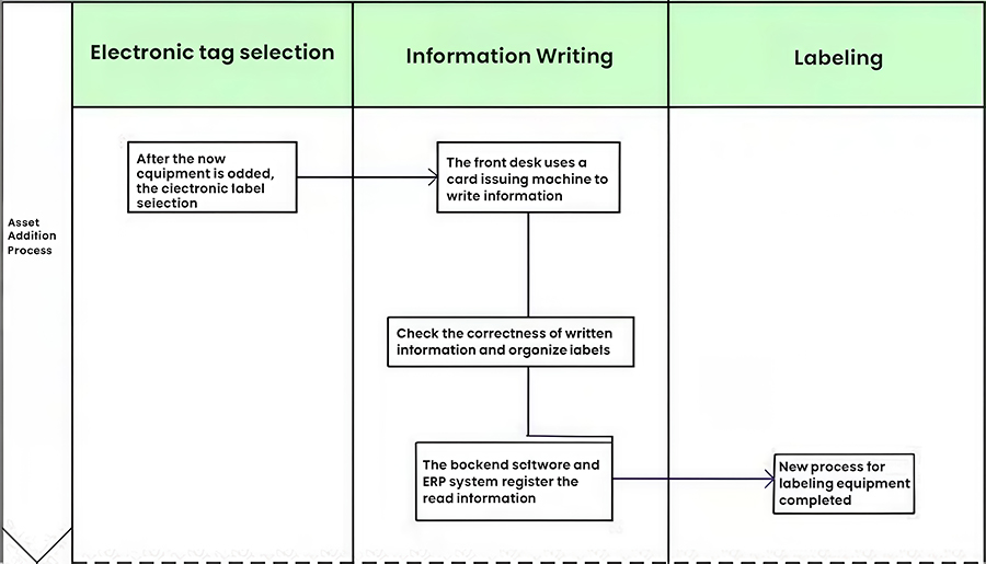
Tag Selection: Assets come in a wide variety of shapes, including field equipment and backup equipment. We use various UHF tags depending on the shape of the object. For metal surfaces, we use metal-resistant tags, while for plastic surfaces, we use standard encapsulated tags.
Writing: Based on customer requirements, we use a card issuing machine to write information to the device tag. We also need to test the issued tag. We can use a handheld reader to test the tag to verify that the data written to the tag is correct. After testing is complete, the backend program will be used to register detailed equipment information in the backend. We will register detailed product information (site name, asset barcode, model, and name) in the backend.
Labeling: Attach or hang the completed asset information label to the asset.
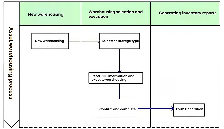
2.2.2 Asset Inbound Operations
The asset management department uses RFID card issuing devices or RFID handheld PDAs to identify the RFID electronic tags on the assets, including the asset's code, name, specifications/model, quantity, and other information. Based on the asset's different inbound business processes, the department will perform the corresponding inbound business processes, handle the relevant inbound procedures, generate the corresponding inbound electronic forms based on the system operations, and simultaneously archive them in the system to organize inbound activity management.
This includes purchase inbound, transfer inbound, lease inbound, outbound repair inbound, lease return inbound, inventory surplus inbound, and other inbound management activities.
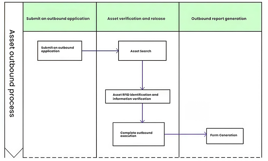
2.2.3 Asset Outbound Operations
The asset management department uses an RFID card issuing device or handheld PDA to verify the asset's RFID tag information, including the code, name, specifications/model, and quantity, based on the outbound voucher issued by the receiving department or the business voucher for accounting adjustments. After verification, the corresponding outbound operation is executed, an electronic form is generated, and the document is archived in the system.
2.2.4 Asset Transfer Operations
The asset transfer process involves moving the asset from one location (Location A) to another (Location B). This process requires two registrations with the interrogator. If the location is within the warehouse, a fixed interrogator can be installed, if located elsewhere, a handheld interrogator can be used. The specific process is as follows:
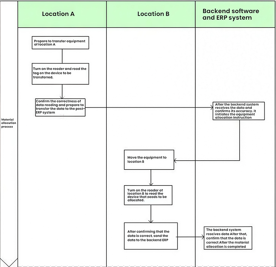
Processing at Location A: Prepare the asset to be transferred. Open the door controlling the travel switch. The interrogator is now in the tag reading state. Remove the asset with the electronic tag and walk out the door. Observe the visual and audible indicators on the interrogator and the LED display showing the asset number to confirm that the electronic tag on the device has been read. The device's information is then recorded by the front-end interrogator and transmitted to the back-end server. Close the door, and the asset has been transferred from the interrogator.
Location B Processing: Bring the asset to the destination to be transferred. Open the door and bring the asset into the interrogator to confirm that the electronic tag on the asset has been correctly read. Similarly, the device's relevant information is transmitted to the back-end server through the interrogator's records. Close the door, and the asset transfer is complete.
2.2.5 Asset Maintenance Operations
Asset maintenance generally has three states: pre-maintenance and during maintenance. Since the destination of an asset after maintenance varies greatly, it may be returned to the original warehouse or transferred to another location. The specific process is not explained in detail here.
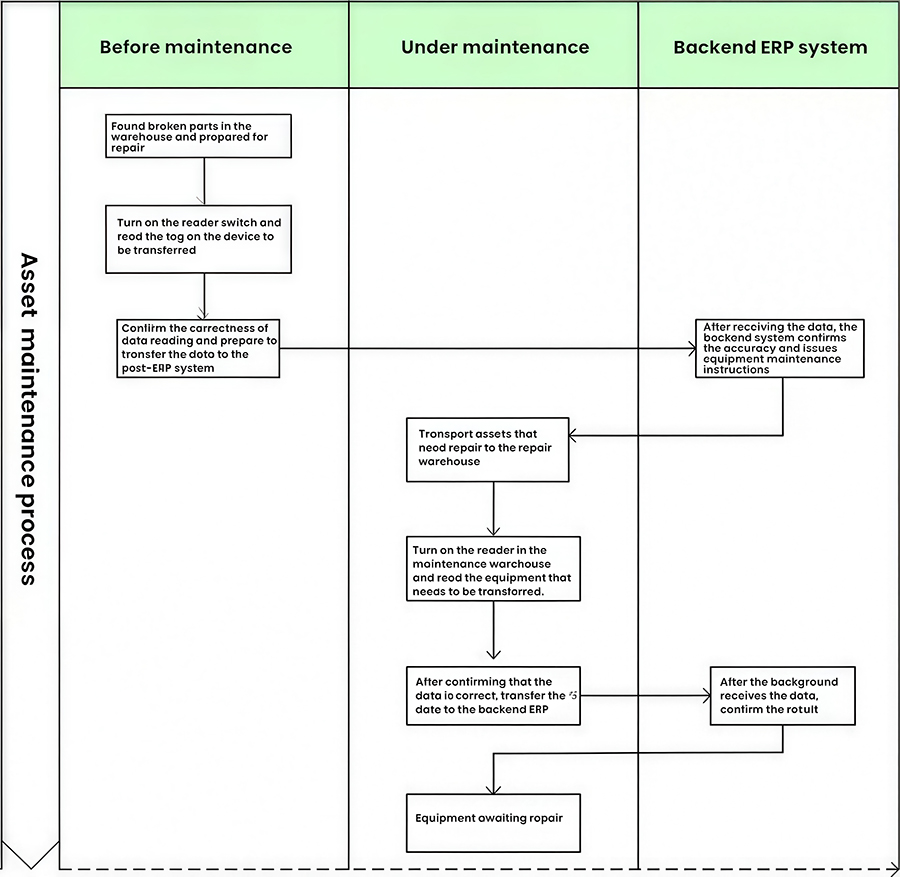
Equipment requiring maintenance: Prepare the faulty device and open the interrogator, enabling it to read tags. Remove the faulty device and observe the digital display on the reader to confirm that the tag is correctly read. The data is transmitted to the backend and automatically registered. By turning off the switch, the faulty device is removed from the reader. During this process, we can monitor the device's fault status in real time in the backend or ERP system.
Devices Under Repair: Bring the device to the warehouse maintenance area, press the reader control button (the indicator light on the button will illuminate), confirm that all tags on the device are correctly read, and press the reader control button again (the indicator light on the button will turn off). The device is now under repair. We use backend data to keep count of the number of devices under repair in the repair warehouse.
Repaired Equipment: Repaired equipment generally has the following destinations:
Placed in the repair warehouse
Returned to the original warehouse
Moved to another location for use
2.2.6 Asset Decommissioning Operations
Equipment decommissioning is primarily registered by two interrogators and involves two main steps:
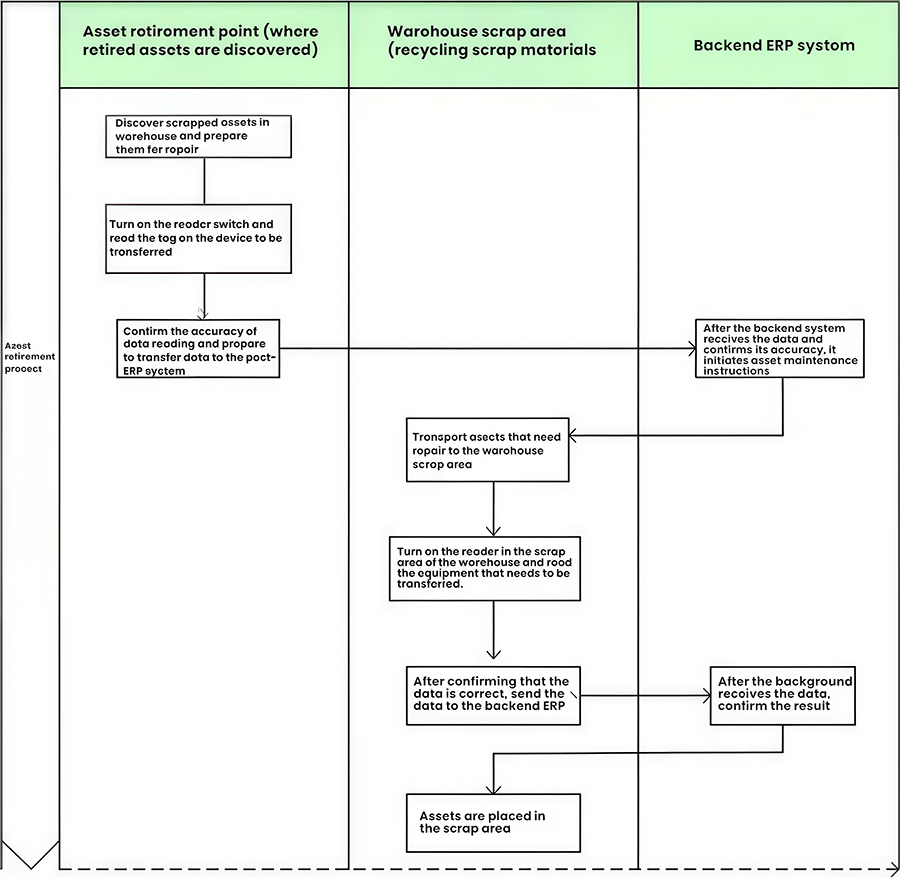
Discovering Decommissioned Assets at the Asset Decommissioning Site: Prepare the decommissioned equipment and turn on the interrogator, enabling it to read tags. Remove the decommissioned equipment and confirm that the tag is correctly read. Turn off the interrogator, and the decommissioned equipment is removed from the interrogator.
Retrieving Decommissioned Assets from the Warehouse Decommissioning Area: Bring the equipment to the decommissioning area and press the interrogator control button to confirm that the tag information on the equipment is correctly read. Press the interrogator control button again to complete the equipment decommissioning operation.
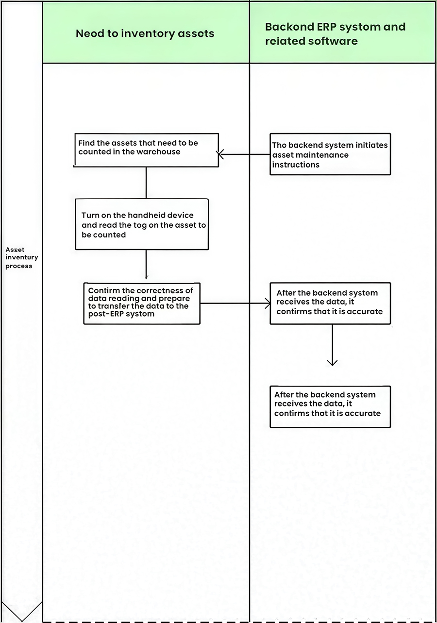
2.2.7 Asset Inventory Operation
Asset inventory is a complex and arduous task. It is typically performed using a handheld device. Press the "I/O" switch to turn it on. At the top of the interface, click to open the Connectivity window, then click Connect GPRS to start the inventory process.
The back-end system generates inventory instructions based on business requirements and issues an inventory work order to the front-end system.
2.3 Software Technical Architecture
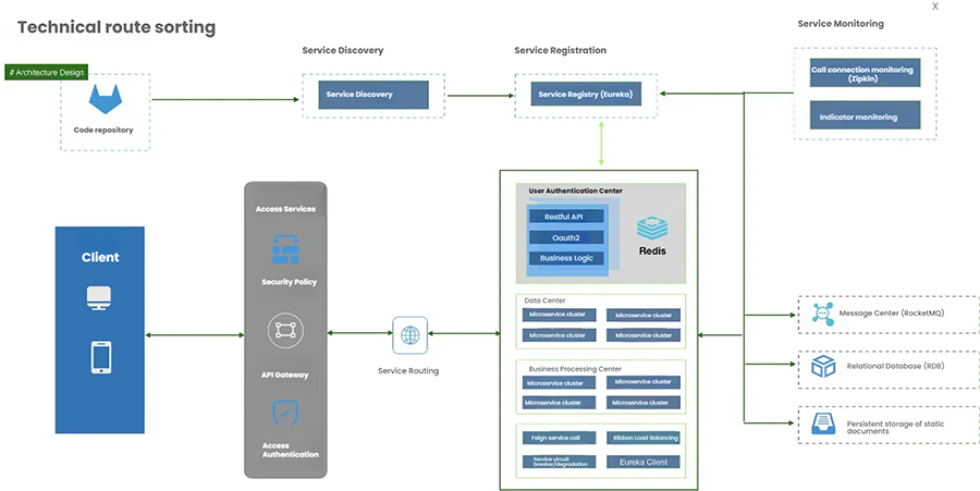
2.3.1 Technical Architecture
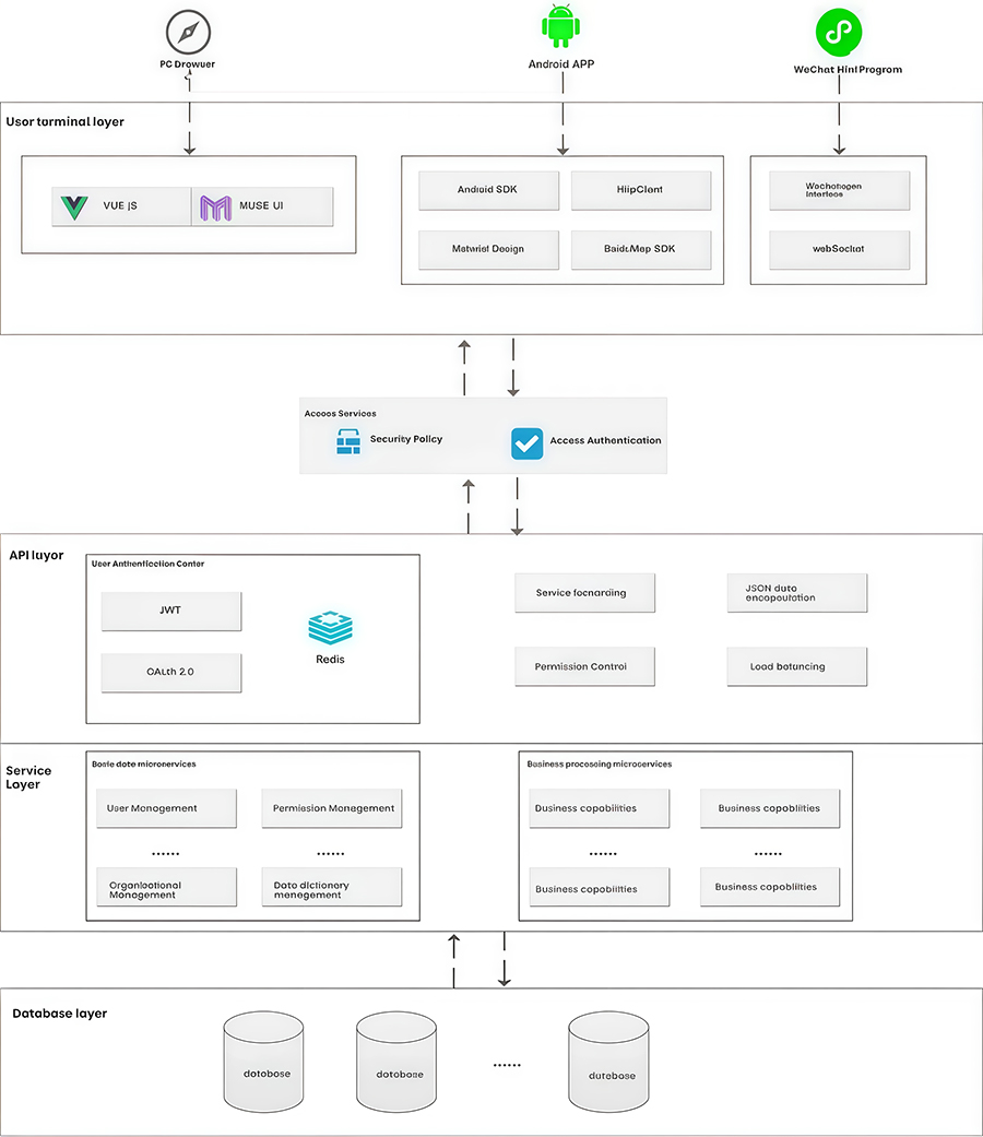
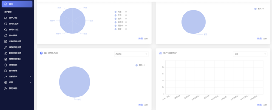
1. Client
The system client is a browser-based, thin, intelligent client application. Built using advanced web technologies, it is a lightweight, user-friendly geographic information client system.
The system client is built on functional components, providing basic map data browsing, querying, and calculation functions. Furthermore, it allows for browsing, querying, and managing logistics information, corresponding surveillance video feeds, and information points within the workspace. Customized business information platforms can be built based on business needs. Sensitivity factor calculations and early warning analysis can be performed based on relevant data, generating relevant maps.
The client itself does not store data, all data is provided by the server. The client utilizes advanced spatial indexing and streaming technologies to retrieve the required data from the server, enabling support for massive amounts of spatial data.
The client can choose whether to save cached data. If cached data is saved, the client can view the locally cached data even when disconnected from the network.
2. Server
The server is based on web services, providing functionality and data to the client via the http/https protocols. The server is developed in Java and SpringCloud.
3. Database and Web Service Proxy
The database and web service proxy are the system's data sources, storing system-related business data such as spatial, attribute, and file data. Monitoring data, related monitoring videos, and logistics location information can be accessed through relevant subsystems, or through adapters, interacting with the system through data proxies. This adapts to the multi-source and heterogeneous nature of monitoring data without modifying existing monitoring software and hardware systems.
4. Permissions Authentication
A. The system's front-end and back-end access utilizes a JWT architecture:
JWT Principles:
After server authentication, a JSON object is generated and sent back to the user. Subsequently, when the user communicates with the server, the client sends the JSON object back in the request. The server relies solely on this JSON object to identify the user. To prevent data tampering, the server adds a signature when generating the object. The JSON object is converted to a string using the Base64 URL algorithm during transmission.
Token Rules:
Token Generation Rules: Username + Password + Private Signature
Token Validation Rules: Token validity verification and username extraction.
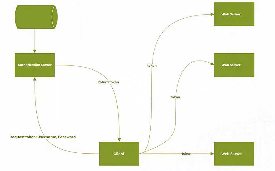
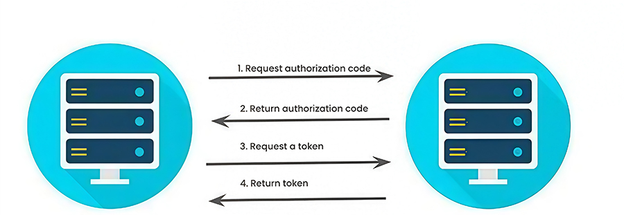
B. Third-Party Access Authentication
The system utilizes spring-security-oauth2 based on the OAuth 2.0 protocol for third-party access authentication.
4. Message Center
The system integrates RocketMQ as a distributed message processing middleware.
Architecture Model:
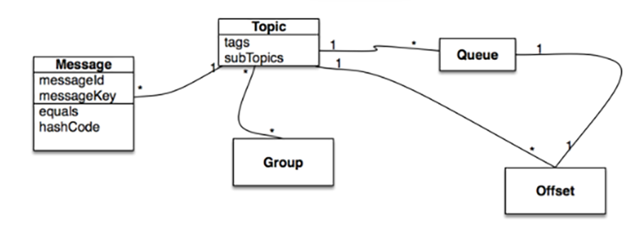
Functionality: Each user acts as a message service consumer, and acts as a message producer based on the topic of their course subscription, producing messages.
Message Push for All Administrators: Public messages are produced as public messages, and all message consumers subscribe by default.
2.3.2 Service Cluster Construction
The application layer primarily implements the separation of page views from control logic and business service calls.
1. Nginx Service Cluster
Provides HTTP access services, including requests for static resources such as static pages, images, scripts, and stylesheets. It also uses Nginx as a reverse proxy, load balancing, and availability management for backend application services.
2. Tomcat Service Cluster
Provides dynamic page processing services. Dynamic page functionality serves as a user access controller, but does not handle transaction management. It is responsible for receiving and parsing client requests, invoking coarse-grained services in the business service layer via RPC, and assembling the processing results from the business service layer into the data format required for front-end page presentation.
2.3.3 Core Business Implementation
The business layer implements the platform's business processes and business logic, and is the core of the entire system. The business layer's technical framework primarily consists of a core framework and business support components. The core framework is the underlying framework that drives the entire business layer, while the business support components are general-purpose and independent technical service components built on top of the core framework.
The core framework primarily utilizes the following technologies:
Spring Cloud: This is an ordered collection of frameworks. It leverages the development convenience of Spring Boot to cleverly simplify the development of distributed system infrastructure, such as service discovery and registration, configuration center, message bus, load balancing, circuit breakers, and data monitoring. These can all be started and deployed with one click using the Spring Boot development style.
Distributed Cache System: This system implements caching services based on self-built Memcache and Redis services, providing high-speed response times for accessing hotspot data. It is used to locally cache business processing results, improving the performance of web applications.
Exception Handling Framework: Centrally captures and handles all types of exceptions during web application operation.
Monitoring and Governance Framework: Based on VMware's HypericHQ IT resource management platform, this framework serves as the monitoring and management portal, allowing operations personnel to quickly understand the status and performance of each service instance. Services are provided through three aspects: site monitoring, service monitoring, and custom monitoring. Through the monitoring and management console, users can view charts of monitored item data for the current service, providing a clear understanding of service operation. Alarm rules can be set to manage monitored item status and obtain timely exception information.
Data Exchange Integration: Provides APIs for sending data to and parsing data from the data exchange platform, simplifying data exchange platform integration development. It also supports integration with the SAP PI module.
RabbitMQ: RabbitMQ is a popular open source message queue system developed in Erlang. RabbitMQ is a standard implementation of AMQP (Advanced Message Queuing Protocol).
On-site Search Engine: Built on the ElasticSearch service, it indexes and searches various data within the platform. ElasticSearch is a search server based on Lucene. It provides a distributed, multi-user, full-text search engine and is a popular enterprise-class search engine, capable of real-time search and offering stability, reliability, and speed.
2.3.4 Application Security Strategy
Application security refers to the necessary security protections for application software running on the platform. This is achieved through security technologies, primarily including encryption, authentication, and security protocols.
1. Encryption Technology
Encryption technology is a basic security measure that can be used by both parties during the information exchange phase as needed. Encryption technologies are divided into two categories: symmetric and asymmetric.
Symmetric Encryption
Symmetric encryption, also known as private key encryption, means that the sender and receiver use the same key to encrypt and decrypt data. Its greatest advantage is its fast encryption/decryption speed, making it suitable for encrypting large amounts of data. However, key management is difficult. If both communicating parties can ensure that the private key is not leaked during the key exchange phase, confidentiality and message integrity can be achieved by encrypting confidential information with this encryption method and sending a message digest or hash value along with the message.
Asymmetric Encryption
Asymmetric encryption, also known as public-key encryption, uses a pair of keys for encryption and decryption, one of which is publicly available (the public key) and the other is kept secret by the user (the private key). The information exchange process is as follows: Party A generates a pair of keys and makes one of them public to the other parties. Party B, having obtained the public key, encrypts the information and sends it to Party A. Party A then decrypts the encrypted information using its private key.
2. Security Protocol
In addition to the various security technologies mentioned above, HTTPS also operates on a comprehensive set of security protocols. Currently, more mature protocols include SET and SSL.
The SSL protocol lies between the transport layer and the application layer and consists of the SSL Record Protocol, the SSL Handshake Protocol, and the SSL Alert Protocol. The SSL Handshake Protocol is used to establish security mechanisms before the client and server actually transmit application-layer data. When a client and server communicate for the first time, they reach agreement on a version number, key exchange algorithm, data encryption algorithm, and hash algorithm through a handshake protocol. They then authenticate each other and use the agreed-upon key exchange algorithm to generate a secret message known only to both parties. The client and server each use this secret message to generate data encryption and hash algorithm parameters.
The SSL Record Protocol encrypts and compresses data sent from the application layer according to the parameters negotiated in the SSL handshake protocol, calculates a message authentication code (MAC), and then sends it to the other party via the network transport layer. The SSL Alert Protocol is used to communicate SSL error messages between the client and server.
The SSL security protocol provides three primary services:
A. Authenticates users and servers, ensuring that data is sent to the correct client and server.
B. Encrypts data to hide the data being transmitted.
C. Maintains data integrity, ensuring that data is not altered during transmission.
D. SSL Security Protocol Steps
3 System Equipment
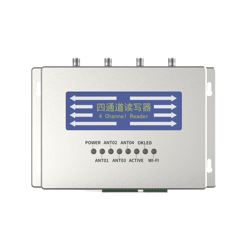
3.1 RFID Tag Conversion System
This RFID tag conversion system effectively writes product information onto RFID tags. It utilizes a unique encryption method for writing item information to securely store a wide range of supply tag information. It supports data conversion and binding for various tags and can be widely used for tag data initialization, data query and modification, and tag function testing, meeting diverse applications in stores, warehouses, and asset management.
The RFID tag conversion system is PC-based and can be integrated with RFID readers/writers, various RFID tag identification devices, and barcode recognition devices as needed to identify RFID tags and process their circulation status. It can also be supplemented by other devices for rapid conversion of barcoded circulation materials within the circulation department. The system should also be capable of scanning barcodes for writing and simple processing as needed.
Features
Scalability and maintainability are key features, and the system equipment can be upgraded through simple hardware upgrades.
RFID tags can be read contactlessly, allowing for quick writing of circulating material information onto the tags.
The system software features the following functions: RFID tag information reading and writing capabilities, enabling integration with asset management systems and the printing of various labels.
The label processing program provides precise operational prompts. If the barcode is successfully entered, the entered barcode information and preset information will be displayed. If the entry fails, a notification will be displayed indicating the failure.
The RFID reader connects to the computer via a standard serial port or USB interface.
The RFID reader and antenna are removable, allowing for device upgrades through simple hardware replacement.
The RFID antenna must be shielded and suitable for a variety of field applications.
It must comply with relevant international industry standards, such as ISO 18000-6C.
The system should support mainstream domestic label printers and offer printing options for different label templates, allowing users to freely select label formats.
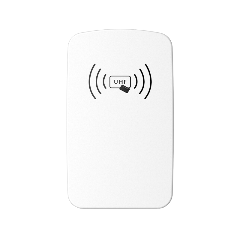
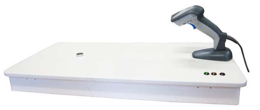
3.2 RFID Handheld
Mid-Range Reader/Writer

Ultra-Long-Range Reader/Writer
Product Features
Used for fixed asset inventory. If there is mismatched information, management personnel can use the handheld reader to conduct on-site verification and modify system or on-site information to complete the asset inventory.
This ultra-long-range reader/writer is based on the Impinj R2000 reader/writer chip and supports BLE 4.0 data communication. It offers low power consumption, multiple data interfaces, and a simple human-computer interface. It can be widely used in various RFID systems. Typical applications include:
Asset Management: Asset management for enterprises in power, rail transit, government, and equipment manufacturing.
Logistics and Warehouse Management: Logistics industries such as goods flow and warehouse management, as well as postal flow management systems for mail, parcels, and luggage.
Supply Chain Applications: Applications in the supply chain.
Product Anti-Counterfeiting Detection: Utilizes the write-protection function within the tag's memory to verify product authenticity.
Other Applications: Widely used in club management, libraries, student enrollment, consumption management, attendance management, and other systems.
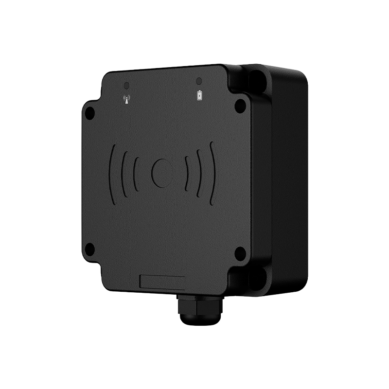
3.3 Fixed RFID Access Control System
Channel Access Control System
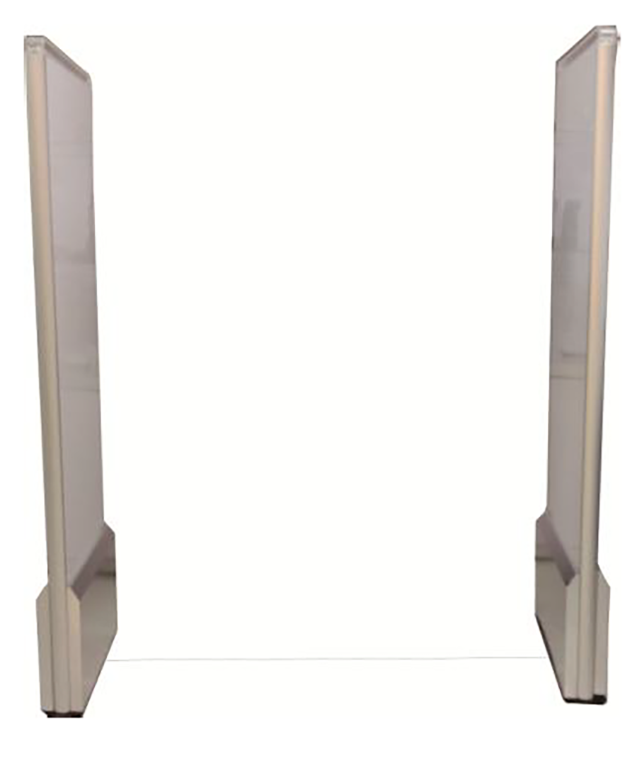
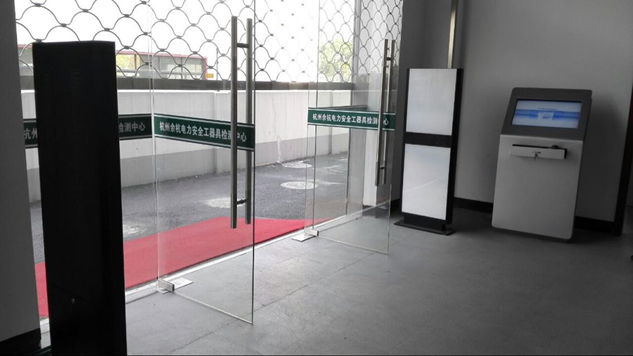
This channel-type RFID access control system is a UHF RFID channel device developed specifically for warehousing and asset management, based on the Impinj R2000 reader/writer chip. It automatically identifies and counts all incoming and outgoing materials, assets, and other commodities, and automatically collects basic data. It features high sensitivity, strong interference resistance, stable performance, and is easy to install, debug, and maintain.
When assets enter and exit the warehouse, the RFID access control system simultaneously identifies the asset's RFID tag information and the RFID tag information of the person entering and exiting the warehouse. Based on the system management permissions, it verifies the identity of the recipient. If there is a discrepancy or if the recipient's information is not detected, the system will automatically alarm.
Compact design, stylish appearance, and easy assembly
3D detection, no false alarms or missed alarms
Flow counting function
Audible and visual alarm function
Sensor activation function
Built-in imported reader for high stability
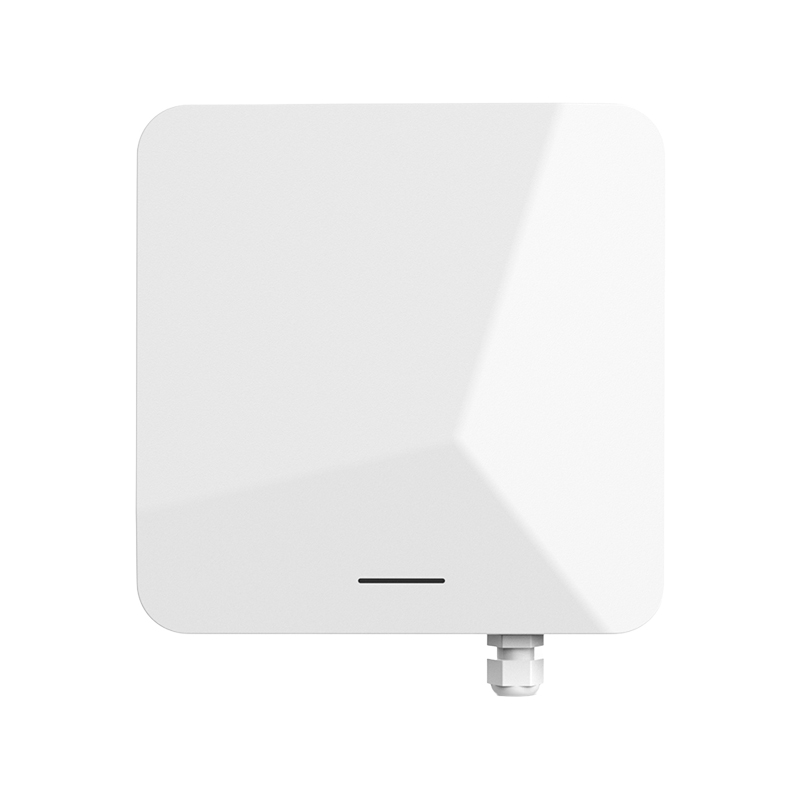
Fixed Reader Customized Access Control System
This fixed, customizable RFID access control system is based on the Impinj R2000 reader/writer chip, a UHF RFID reader/writer developed specifically for warehousing and asset management. Designed and constructed to order on-site, it automatically identifies and counts all incoming and outgoing materials, assets, and other goods, automatically collecting basic data. It features high sensitivity, strong interference resistance, stable performance, aesthetics, and excellent concealment.
When assets enter and exit the warehouse, the RFID access control system simultaneously identifies the asset's RFID tag information and the RFID tag information of the person entering and exiting the warehouse. Based on system management permissions, it verifies the identity of the recipient. If there is a discrepancy or if the recipient's information is not detected, the system will automatically alarm.
3D detection, no false alarms or missed alarms
Flow counting function
Sound and light alarm function
Sensor activation function
Built-in imported reader, high stability
3.4 RFID Tags
1. Asset Management Tags
We offer a wide variety of asset management tags, mainly divided into two types: anti-metal tags and standard self-adhesive tags. Customizable sizes are available and compatible with EPCGlobal Gen2 and FSTC industry standards. Details are as follows:
Anti-metal Tag Technical Parameters
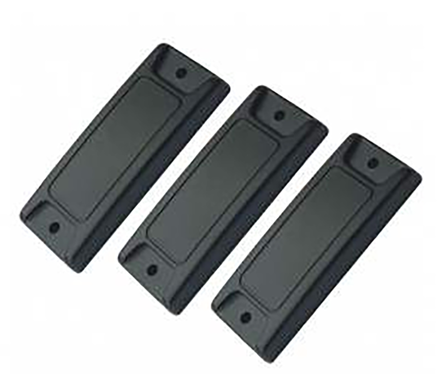
ABS Anti-metal Tags

Flexible Anti-metal Tags
Anti-metal material management label | |
Serial number | Require |
1 | Label material: ABS or PCB |
2 | Operating frequency band: 920MHz-925MHz |
3 | Supported protocols: EPCGlobal C1 Gen2 |
4 | Reading distance: 1-5m (related to reader configuration) |
5 | Working mode: read and write, can be directly pasted on the metal surface |
6 | Anti-collision: support multiple tags |
7 | Working temperature: -10℃~+70℃ |
8 | Storage temperature: -20℃~+85℃ |
9 | Available data area: up to 512 bits |
10 | Tag Identifier: (TID) 64 bits |
11 | Working mode: read and write |
12 | Data retention time: >10 years |
13 | Anti-collision mechanism: suitable for multi-tag reading |
Self-adhesive Electronic Label Technical Parameters
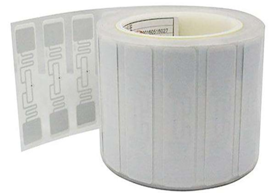
Ordinary self-adhesive labels | |
Serial number | Require |
1 | Label substrate: PET |
2 | Antenna Material: Aluminum |
3 | Packaging material: PET, coated paper or synthetic paper |
4 | Working temperature: -10℃~+70℃ |
5 | Storage temperature: -20℃~+85℃ |
6 | Operating frequency: 920MHz-925MHz |
7 | Supported protocols:EPCGlobal C1 Gen2. |
8 | Reading distance: 1m~5.5m (related to reader configuration) |
9 | Available data area: up to 512 bits |
10 | Tag Identifier: (TID) 64 bits |
11 | Working mode: read and write |
12 | Data retention time: >10 years |
13 | Anti-collision mechanism: suitable for multi-tag reading |
2. Personnel Management Tags
Personnel Management Tags
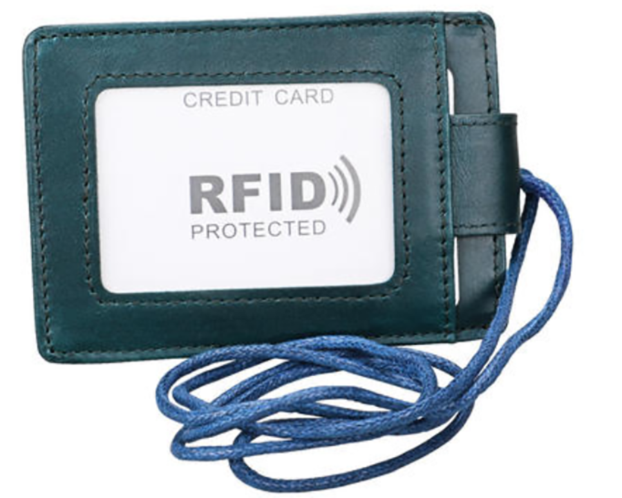
Personnel Management Tags | |
Serial number | Require |
1 | Label substrate: PET |
2 | Antenna Material: Aluminum |
3 | Packaging material: PVC+PET card packaging |
4 | Working temperature: -10℃~+70℃ |
5 | Storage temperature: -20℃~+85℃ |
6 | Operating frequency: 920MHz-925MHz |
7 | Supported protocols:EPCGlobal C1 Gen2. |
8 | Reading distance: 1m~5.5m (related to reader configuration) |
9 | Available data area: up to 512 bits |
10 | Tag Identifier: (TID) 64 bits |
11 | Working mode: read and write |
12 | Data retention time: >10 years |
13 | Anti-collision mechanism: suitable for multi-tag reading |
3.5 RFID Printers
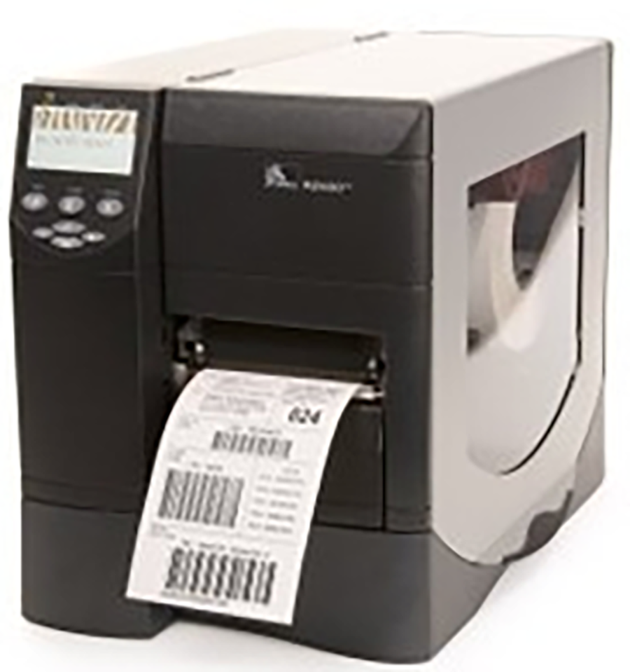
Product Types RFID Printer
Resolution: 203dpi
Print Method: Direct Thermal and Thermal Transfer
Print Speed: 254mm/s
Maximum Print Width: 104mm
Maximum Print Length: 3.99m
Barcode Type: 1D Barcode
Fonts/Character Set: Standard Fonts: 7 bitmap fonts, 1 smooth scalable font (CG Triumvirate Bold Condensed)
Character Set: IBM Code Page 850 International Character Set
European and Asian Font Sets
Supports user-defined fonts Graphics, including custom logos
ZPL II drawing commands, including boxes and lines
Communication Interfaces USB 2.0, serial, and parallel
Storage 16MB RAM, 8MB Flash
CPU 32-bit processor
Media Sensors Reflective, transmissive